Chapter 1. Tools Utilized
66
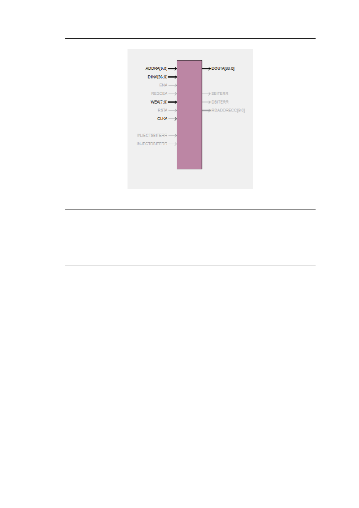
Figure 5.7: The data memory
c o m p o n e n t d a t a _ m e m o r y
p o r t (
c l k a
: in s t d _ l o g i c ;
wea
: in s t d _ l o g i c _ v e c t o r (7 d o w n t o 0);
a d d r a : in s t d _ l o g i c _ v e c t o r (9 d o w n t o 0);
d i n a
: in s t d _ l o g i c _ v e c t o r (63 d o w n t o 0);
d o u t a : out s t d _ l o g i c _ v e c t o r (63 d o w n t o 0)
);
end c o m p o n e n t ;
Figure 5.8: The data memory VHDL interface
The data memory was generated similarly with the difference of the write enable signal.
The CORE Generator offers the choice to write single bytes of the words stored. For
example a 64bit word that is stored in the memory, if a change had to be made in the
first 32 bits of the word. the processor had to read the memory first, alter the bits and
then store it again. By using this feature single byte word updates are possible and since
the processor makes extensive use of subwords and parallel data updating, this feature is
very helpful. For this reason the illegal trap that had to be raised on unaligned memory
accesses according to [
] is ignored. Figure
shows the memory block and figure
shows the VHDL interface. Both memories operate at a fixed 144MHz speed.