Chapter 4. The Processor Customization
53
1) l o a d i . k .0
000 0 0 0 1 0 1 0 0 0 0 1 00 1 0 0 1 0 0 1 0 1 0 0 1 0 1 0 1
2) l o a d i . k .1
000 0 0 0 1 0 1 0 0 0 0 1 01 0 0 1 0 1 0 0 1 0 1 0 0 1 0 0 1
3) l o a d i . k .2
000 0 0 0 1 0 1 0 0 0 0 1 10 1 1 0 1 1 1 1 1 1 1 1 1 1 1 1 0
4) l o a d i . k .3
000 0 0 0 1 0 1 0 0 0 0 1 11 0 1 0 0 1 0 1 0 0 1 0 1 0 1 0 0
5) l o a d i . k .0
000 0 0 0 1 0 1 0 0 0 1 0 00 0 0 1 0 0 1 0 1 0 1 0 1 0 1 0 0
6) l o a d i . k .1
000 0 0 0 1 0 1 0 0 0 1 0 01 0 1 0 1 0 1 0 1 0 0 0 0 0 0 0 0
7) l o a d i . k .2
000 0 0 0 1 0 1 0 0 0 1 0 10 0 0 1 0 1 0 1 0 1 0 1 1 0 0 0 0
8 ) l o a d i . k .3
000 0 0 0 1 0 1 0 0 0 1 0 11 1 1 0 1 0 1 0 1 0 1 0 1 0 1 1 1
9) and
000 1 1 0 0 0 0 0 0 0 1 1 0 0 0 0 1 0 0 0 1 0 1 1 0 0 0 0 00
Figure 4.5: The ”and” machine code
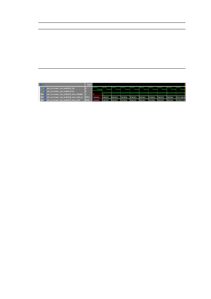
Figure 4.6: The processor initialization process
4.4.2
Execution Testing
In order to fully test the processor a compiler is required, however this was not imple-
mented due to time constraints. All the instructions have been verified individually and
found to operate properly. A sample execution follows which implements a simple and
instruction. This specific example was chosen because it utilises many components of
the processor: Register file read/write, program counter incrementation/stall, instruc-
tion memory initialization/read, ALU and instruction. Figure
shows the instructions
used along with the instruction codes.
The first four instructions load the register ”00001” with 16 bits of data each filling a
different subword. The next four instructions fill the register ”00010” with data similarly
to the first to form another random 64 bit number. The final instruction is the ”and”
instruction which ands the values in the registers ”00001” and ”00010”, and then stores
the result in the register ”00011”. All instructions are predicated to the ”000” register
which is hardwired to ’1’ so as to be always executed.
The first step in the processor function is to reset the top module. Second step is to
initialize the memory and insert all the instruction in consecutive instruction memory
slots, starting from position ”000000000” up to position ”000001000”. These steps are
shown in figure
. The simulation lasts 1000ns, since the clock step is 100ns nine cycles
are for the memory initialization process and one for the resetting.