Chapter 3. The FPU
43
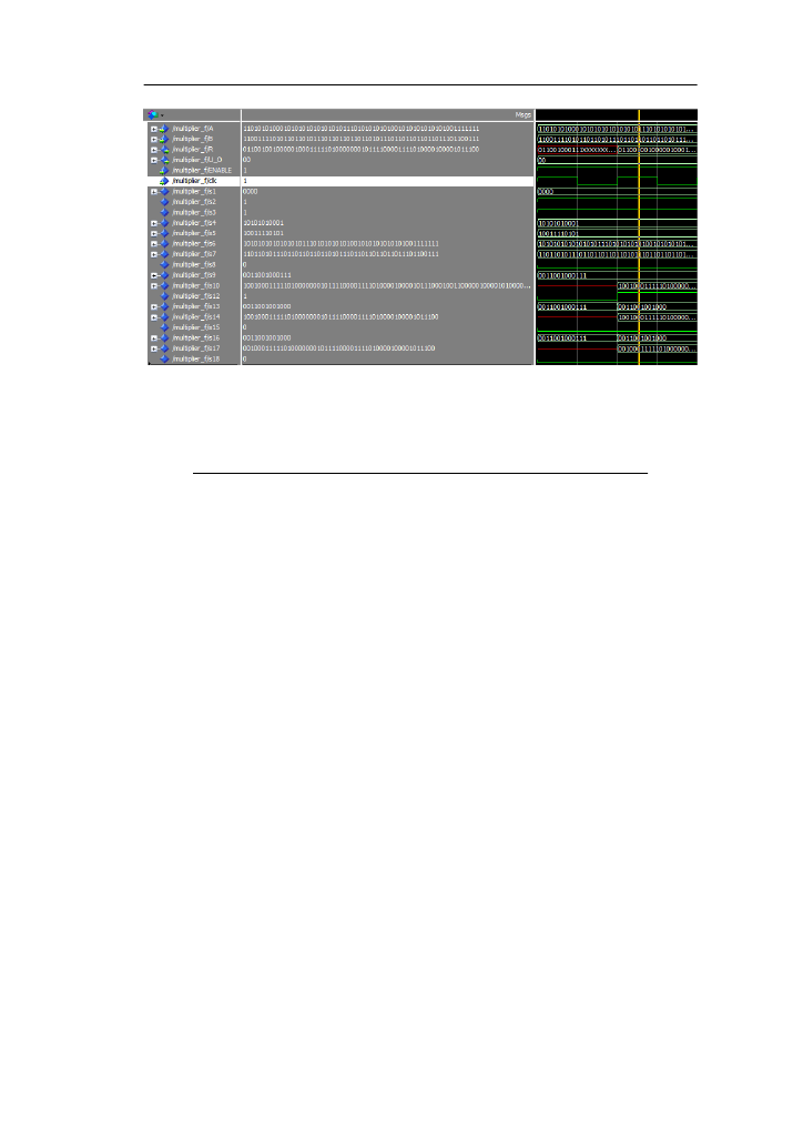
Figure 3.4: The FPU multiplier simulation
Table 3.3: Device Utilization Summary for the FPU Divider
Logic Utilization
Used
Available
Utilization
Number of Slice Registers
446
93120
0%
Number of slice LUTs
2382
46560
5%
Number of used LUT-FF pairs
351
2477
14%
Number of bonded IOBs
201
240
83%
Number of BUFG/BUFGCTRLs
2
32
6%
Number of DSP48E1s
15
288
65
is shown in Figure
and the whole division module can be found at Appendix A
This module produces one bit per entry of the final result.
The first step in calculating the result is similar to this of the multiplication. The
exponent is calculated with the following formula: E
R
= E
A
− E
B
+ E
bias
. As with
the multiplication since the actual exponents are in the form of E + E
bias
when two
exponents are subtracted the two E
bias
cancel each other out, so an extra E
bias
must be
added to the final result.
The next step is calculating the division between S
A
and S
B
. Since the two significands
are in the range of [1,2) the result will be S
R
will be in the range (0.5,2), i.e. if not
already normalized, it will require a left shift by just one place. The final step is to
normalize and round the result which is performed in the final cycle.
The divider operates at a maximum frequency of 254.704MHz and the power consump-
tion is 1.293Watts.Table
shows the area utilization by the divider.